
This paper introduce NFP, a high performance framework, that embraces NF parallelism to reduce NFV latency.
Introduction
NFP framework consists of three logical components including
- a policy specification scheme: intuitively repre- senting sequential or parallel chaining intents of network opera- tors to improve the parallelism optimization effect of NFP
- NFP orchestrator: can identify NF dependency and automatically compile policies into high performance service graphs with parallel NFs.
- NFP infrastructure: efficiently supports NF paral- lelism based on light-weight packet copying, distributed parallel packet delivery, and load-balanced merging of packet copies.
Motication and challenges
policy definition
Order(NF1, before, NF2)
This Order rule type can be used to describe a sequen- tial NF composition intent.
Priotity(NF1 > NF2)
Therefore, network operators can specify the Priority(IPS > Firewall) rule to parallelize the two NFs while indicating the system should adopt the processing result of IPS during conflicts.
Position(NF, first/last)
Therefore, network operators can specify the Priority(IPS > Firewall) rule to parallelize the two NFs while indicating the system should adopt the processing result of IPS during conflicts.
Orchestrator design
NF parallelism analysis
To analyze whether two NFs are parallelizable, we propose a result correctness principle: Two NFs can work in parallel, if parallel execution of the two NFs results in the same processed packet and NF internel states as the sequential service composition.
Resource overhead optimization
dirty memory reusing
If two NFs read or write different fields of a packet, they can operate on the same packet copy. We name this optimization technique as Dirty Memory Reusing, which could reduce packet copying necessities.
Header-only copying
only few NFs modify packet payload, and packet header only occupies a small percentage of the packet.
NF parallelism identification algorithm
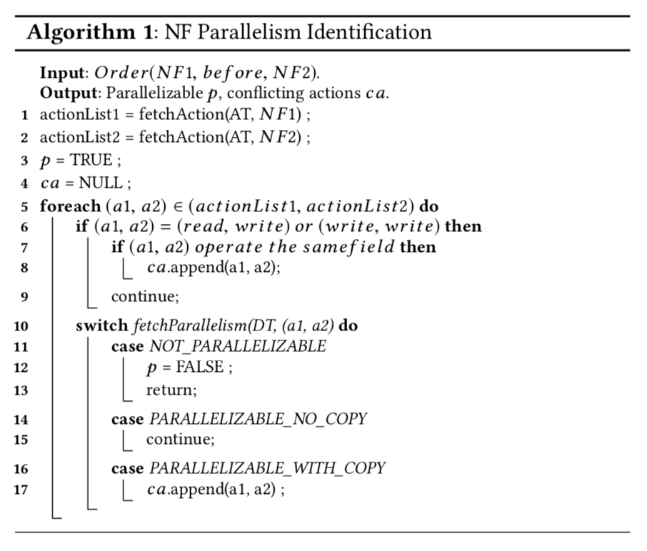
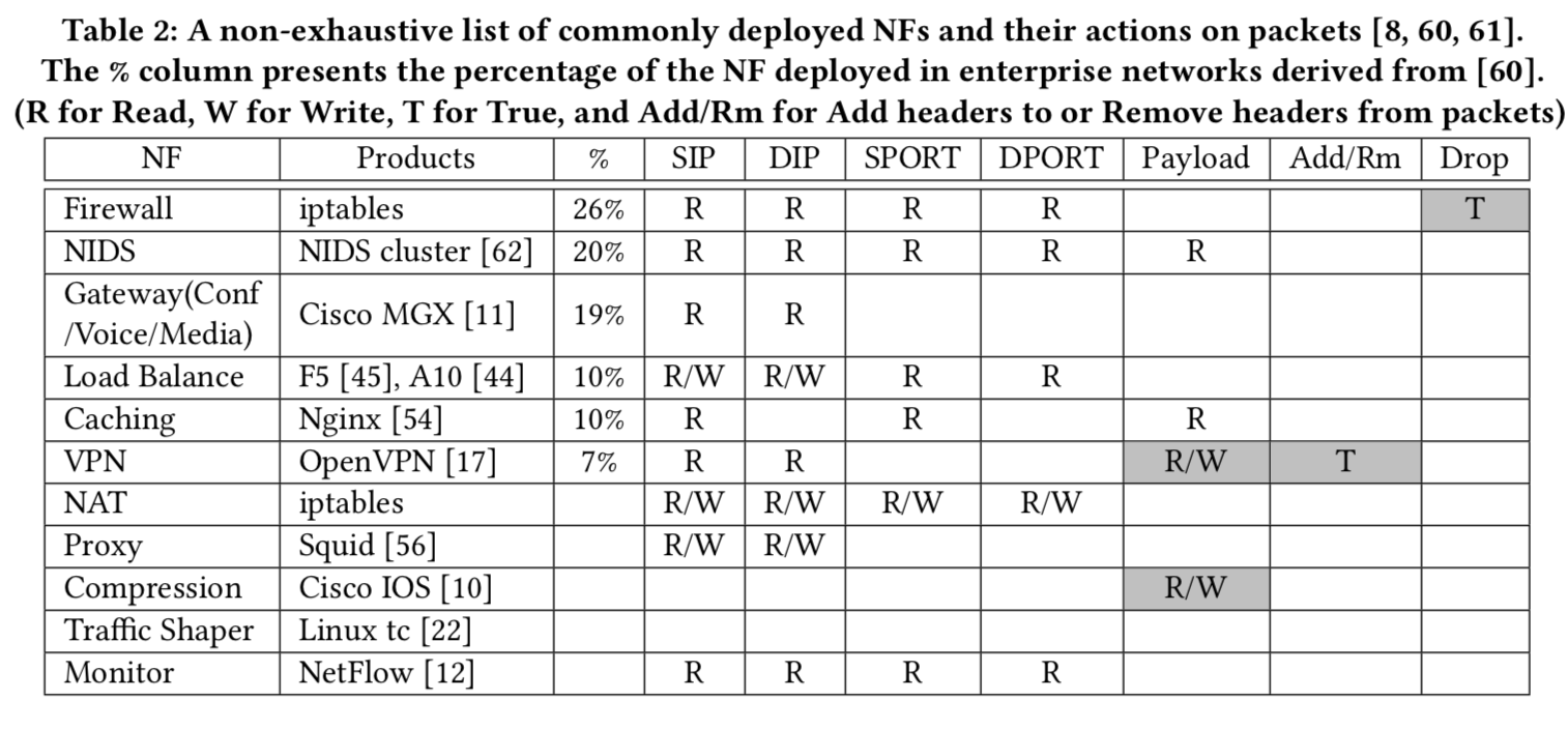
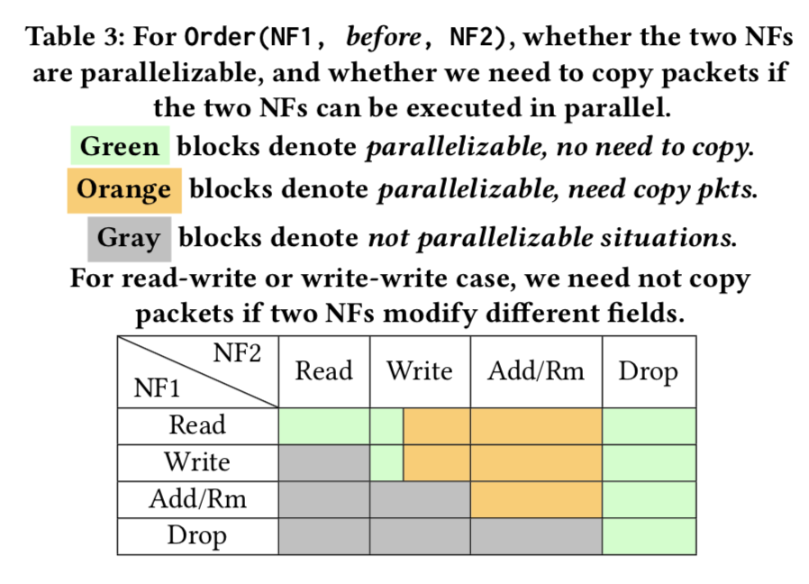
NFP orchestrator maintains an NF action table (AT, i.e. Table 2) and an action dependency table (DT, i.e. Table 3), and takes an Order rule as input.
First, the algorithm fetches all the actions of the two NFs from AT (lines 1-2). Then it exhaustively goes over all action pairs from the two NFs (lines 5-17) to figure out the parallelism possibility for the two NFs based on the DT. For the read-write or write-write case, we need to further decide if the two actions operate on the same field (lines 6-9). If the two NFs can be parallelized with packet copying, we need to record the conflicting actions (lines 16-17). Finally, the algorithm generates the output of whether the two NFs are parallelizable (p) and possible conflicting actions (ca), whose existence indicates the necessity of packet copying.
For two NFs specified in a Priority rule, we still need to decide whether they require packet copying to work in parallel. In this situation, we still use Algorithm 1 to identify possible conflicting actions of the two NFs.
service graph construction

transforming policies into intermediate representations
We design two types of intermediate representations to store NFP policies.
For Position rules, we maintain the NF type and its position in the left representation block, which records the placement of a single NF.
The Order and Priority rules are finally transformed into the representation shown on the right, which reveals the relationship between two NFs.
compiling intermediate representation into micrographs
Then we concatenate intermediate representations with overlapping NFs into a micrograph by using overlapping NFs as junction points. There are three types of micrograph structures including Single NF (e.g. NF1, NF8), Tree (e.g. NF2, NF3 and NF4), and Plain Parallelism (e.g. NF5, NF6 and NF7).
We exhaustively check dependencies of all leaf NF pairs with the same root to figure out whether the leaf NFs can work in parallel. For plain parallelism micrographs, we exhaustively check the dependencies of all NF pairs to calculate how many packet copies are needed for them.
merging micrographs into the final graph
NFs assigned by Position rules are first placed in the head/tail of the chain (NF1). Then we wrap up each remaining micrograph (including free NFs) as one NF, and exhaustively check the dependency of each micrograph pair to decide their parallelism. If any dependency is detected be- tween micrographs, network operators will be informed to further regulate execution priority of them. Finally, we place independent micrographs in parallel (Figure 2).
infrastructure design

packet classification
The classifier module takes an incoming packet from the NIC and finds out the corresponding service graph information for the packet, including how many packet copies are expected in the merger, how to merge different copies of a packet, and the first hop(s) of the service graph.
Therefore, the classifier maintains a Classification Table (CT) shown in Figure 4 to store the match fields (e.g. five tuple), the total packet copy count to be received in the merger, the merging operations (MOs) to merge packet copies (details are presented in §5.3), and the actions indicating the first NF(s) of the service graph, based on which the classifier sends the packet into the entrance of the graph.
MID
to avoid repeated storage of the service graph information
PID
to identify each packet in a flow
packet delivery among NFs
Therefore, the NFP classifier attaches a 64 bits metadata to a packet, recording the MID, PID and version of a specific packet copy.
After packet processing, the NF could delegate the packet to the NF runtime, which copies the packet reference to the next NFs’ ring buffer to realize packet forwarding.
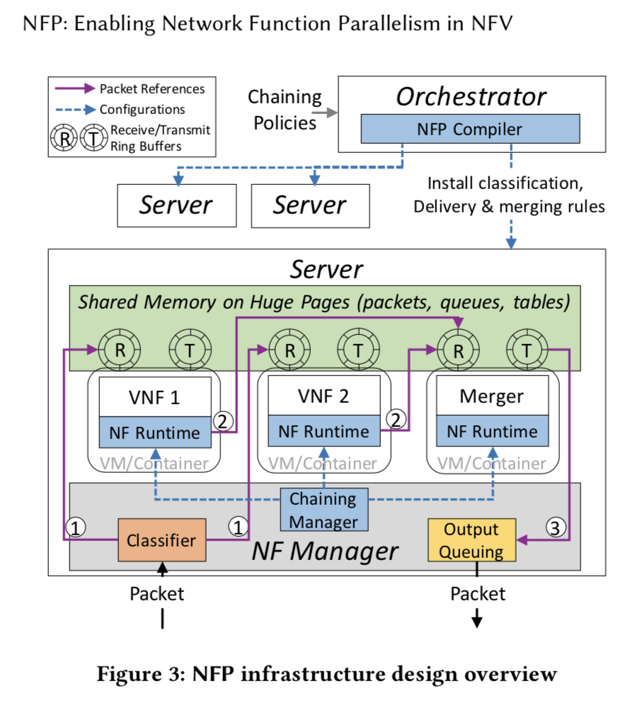
Each NF runtime maintains a forwarding table (FT) (see Fig- ure 4), which stores a local view of the entire service graph. The global forwarding table is generated at the end of the service graph construction process (§4.4.3), and then statically installed to the Chaining Manager (as shown in dashed blue line in Figure 3). The chaining Manager splits the global table and installs the forwarding rules to each NF runtime. When an NF delegates a packet to the NF runtime, the MID in the packet metadata is used to look up the actions in FT.
we design four actions
- ignore
- distribute
- copy
- output
load balanced packet merging
packet merging
When the current count field in AT reaches the total count recorded in CT referenced by the key of MID, the merger will merge the packet copies according to the merging operations (MOs) in the CT.
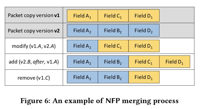
The original packet copy is tagged as version v1 by the classifier, and MOs record how to merge the rest of packet copies into v1 to create the final output.
MOs include three types of operation
- modify(v1.A, v2.A)
- add(v2.B, before/after, v1.A)
- remove(v1.C)
To deal with NF dropping actions on a packet p, we enable the NF runtime to send a nil packet, which has the same metadata as p to the merger. When the merger receives a nil packet, it considers the packet p as dropped. We then remove the related AT entry and release the memory of all received packet copies.
merger load balancing
we propose to deploy multiple mergers in one NFP server and design a merger agent to balance the load among the instances. A merger instance maintains a local AT, and could merge any packet from any service graph.
integrating network functions into NFP
Operators can run the inspector against their NF code to automatically generate an action profile, which can be registered into NFP to integrate the new NF into NFP.


近期评论